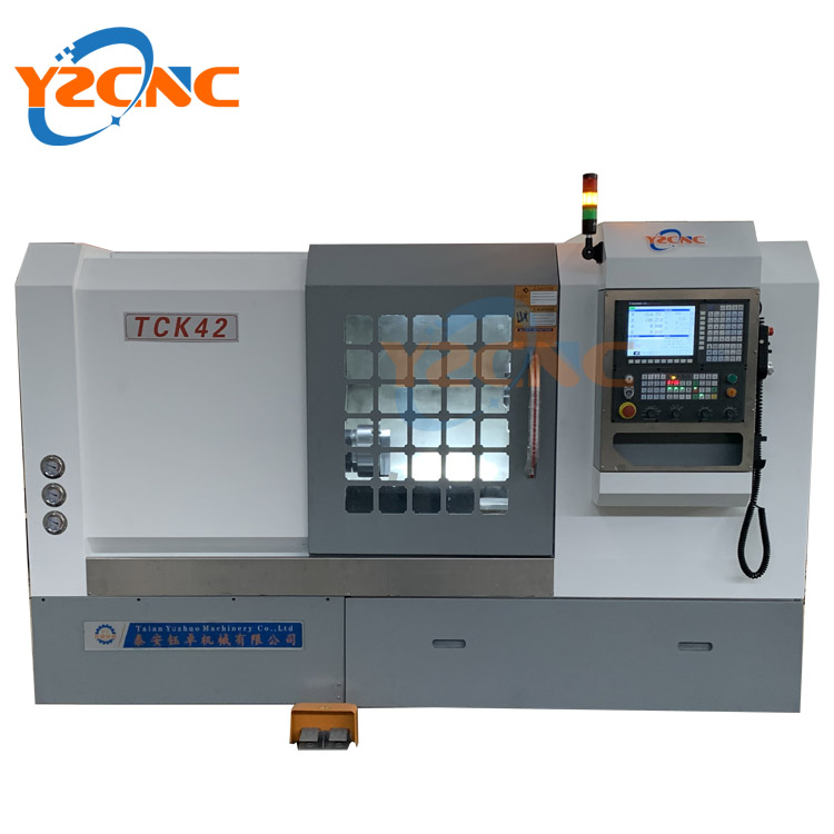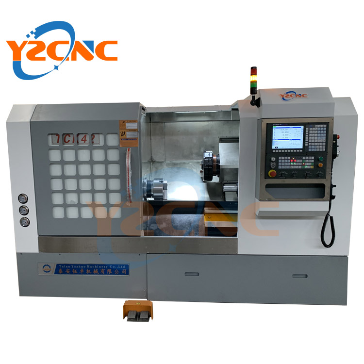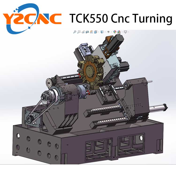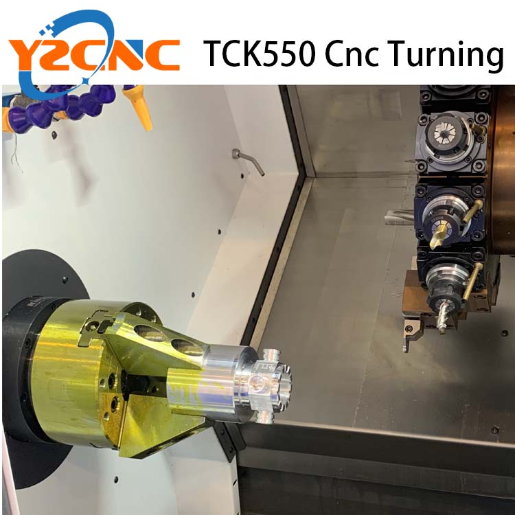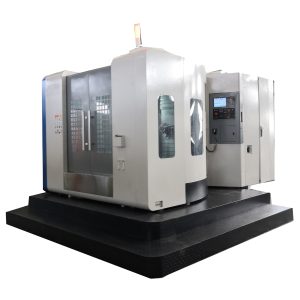
TCK42 Slant Bed Cnc Lathe
TCK42 Slant Bed Cnc Lathe Standard configuration
(bed tilted 30 degrees and 45 degrees)
45 degrees Standard machine configuration
1. GSK988TA/GSK980TDC/Siemens/Fanuc
2. Hydraulic chuck, hydraulic turret, 8 stations, hydraulic tailstock
3. Automatic chip conveyor
30 degrees (12-station power turret) can be equipped with Y-axis as an option
GSK988TA/SIEMENS/SYNTEC
- VMC Series Vertical Machining Center
- VTC Series Vertical CNC Lathe Machine
- TCK Series Slant Bed CNC Lathe
- WRC Series Wheel Repair CNC Lathe
- QK Series Large Bore Pipe Thread Lathe
- CK Series Horizontal CNC Lathe Machine
- CK Series Heavy Duty CNC Lathe
- CA Series Universal Lathe
- Drilling and Milling Machine
- Sawing Machine
- Slotting Machine and Shape
- Radial Drilling Machine
GET A QUICK REQUESTS
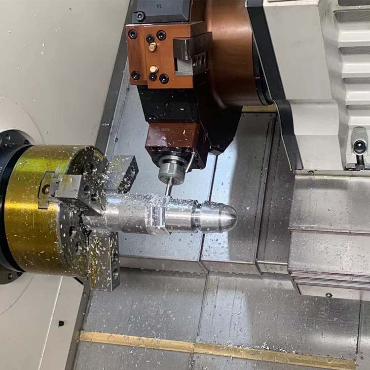
TCK42 Slant bed CNC lathe, also known as inclined bed CNC lathes, are a popular type of CNC machine tool that features a slanted bed for supporting the workpiece and cutting tool. This design offers several advantages and characteristics that make it ideal for a variety of machining applications.
 Improved Rigidity and Stability
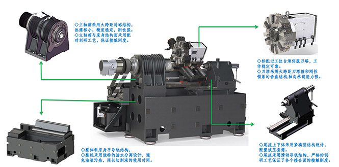
The slanted bed design of a CNC lathe improves the rigidity and stability of the machine. The angled bed helps to distribute the weight of the workpiece and cutting forces more evenly across the bed, reducing vibrations and ensuring accurate cutting. The slanted bed also provides better support for the carriage and cutting tool, resulting in improved precision and surface finish.
Better Chip Disposal
The slanted bed design of a CNC lathe also allows for better chip disposal. The chips generated during cutting are directed away from the cutting area and toward the chip conveyor, which makes cleaning and maintenance easier. This can improve the efficiency and productivity of the machine, as well as the safety of the operator.
Improved Accessibility
The slanted bed design of a CNC lathe also improves accessibility to the cutting area. The angled bed allows for better visibility and easier access to the cutting tool, workpiece, and chuck. This makes it easier to set up and adjust the machine, as well as monitor the cutting process.
Better Thermal Stability
The slanted bed design of a CNC lathe also offers better thermal stability. The angled bed helps to dissipate heat generated during cutting, which reduces thermal deformation and ensures dimensional accuracy. This can improve the quality and precision of the machined parts.
Reduced Floor Space Requirements
The slanted bed design of a CNC lathe also allows for reduced floor space requirements. The compact design of the machine takes up less floor space compared to other types of CNC lathes, which can be beneficial for smaller machine shops or those with limited floor space.
Increased Flexibility
The slanted bed design of a CNC lathe also provides increased flexibility for machining different types of parts. The angled bed can accommodate larger workpieces with a smaller footprint, and can also provide better access to certain areas of the part that may be difficult to reach with a horizontal bed lathe.
Improved Ergonomics
Finally, the slanted bed design of a CNC lathe can improve ergonomics for the operator. The angled bed can be positioned at a more comfortable working height, reducing strain and fatigue on the operator. Additionally, improved accessibility and chip disposal can also reduce the risk of injury or strain.
In summary, the slant bed CNC lathe offers several advantages and characteristics that make it a popular choice for a variety of machining applications. Its improved rigidity and stability, better chip disposal, improved accessibility, better thermal stability, reduced floor space requirements, increased flexibility, and improved ergonomics make it an attractive option for many machine shops.
TCK42 Slant Bed Cnc Lathe Specification
| ITM | UNIT | TCK42(30 degree) Y -AXIS TCK42 (45degree) without Y-AXIS | TCK550 30 degreesY-AXIS | ||
| Work Range | Max. swing dia. over bed | mm | 420 | 560 | |
| Max. swing dia. over slide | Mm | 195 | 360 | ||
| Max. cutting dia. Of disc type parts | mm | 420 | 550 | ||
| Max. cutting dia. Of axle type parts | mm | 195 | 360 | ||
| Distance between centers | mm | 500/1000/1500 | 500/1000/1500 | ||
| X/Z/Y Axis | X axis travel | mm | 240 | 320 | |
| Z axis travel | mm | 550/1050/1550 | 550/1050/1550 | ||
| Y axis | mm | ±35 | ±45 | ||
| X Z Fast feed | mm | 12000 | 12000 | ||
| Spindle | Spindle bore | mm | 56 | 66(A2-6)/86(A2-8) | |
| Max through hole bar diameter | mm | 40 | 50(A2-6)/75(A2-8) | ||
| spindle nose type | A2-5 | A2-6/A2-8 | |||
| spindle speed | rpm | 4000 | 3000 | ||
| Main motor power (C AXIS) | kw | 5.5KW Servo | 7.5KW Servo | ||
| accuracy | X Z axis positioning accuracy | mm | 0.012 | 0.012 | |
| X Z repeatability | mm | 0.003 | 0.003 | ||
| Diameter uniformity | mm | 0.03/300 | 0.03/300 | ||
| Flatness | mm | 0.03/300 | 0.03/300 | ||
| Number Turret | 12 servo power turret | 12 servo power turret | |||
| power turret | turret type | BMT40 Y AXY-AXIS
| BT45/BT55 Y AXIS | ||
| Outer diameter Shank diameter | 20X20 | 20X20/25X25 | |||
| Inner shank diameter | 25 | 32 | |||
| Driven tool | End face driven tool | ER20/3000RPM | ER25/3000RPM | ||
| Side face driven tool | ER20/3000RPM | ER25/3000RPM | |||
| Chuck | mm | Hydraulic Chuck(8inch) | Hydraulic Chuck 10 inch | ||
| Machine size | mm | 2500/3000/3500x1800X1800 | 2700/3200/3700X2100X1900 | ||
| 3.2T/3.7/4.2 | 3.8/4.3/4.8 | ||||
Related Products
